Beginning in the early 1990s connecting to the internet began as a simple direct path. Nowadays things have advanced and have become more complex but also more capable. Instead of a single Ethernet connection to the internet, microcontrollers and other devices can connect through a long list of protocols: Bluetooth, WiFi, BLE, ZigBee, 3G, 4G, 5G, NFC, RFID, SigFox, DigiMesh, Thread, and 6LoWPAN to name a few. Each of these connections plays a valuable role for device connection and data transmission, but one budding protocol we would like to highlight is LoRaWan.
Like those listed above, LoRaWAN is a wireless connection network for data communication to the internet. LoRaWan is quickly set itself apart as it becomes known and tailored to IoT (Internet of Things) applications that require long-range and low-power connectivity to the internet without WiFi. LoRaWan is a great answer for remote battery-powered sensors or devices that communicate over long distances or in remote places. LoRaWan said simply, packages data are sent, when needed, over long distances to the nearest, most available gateway which forwards said packets of data to the server for storage, computation, or visualization.
To become more familiar with LoRaWAN, let’s got back to 2009 when the precursor to LoRaWAN called LPWAN began in France:
- LPWAN is a wireless telecommunication wide area network designed to allow long-range communications at a low bit rate for things (connected objects), such as sensors operating on battery with low power requirements.
- LPWAN enables connectivity for networks of devices that require less bandwidth than what the standard home equipment provides
- LPWAN networks also support more devices over a larger coverage area than consumer mobile technologies and have better bi-directionality capabilities
- Networks like WiFi and Bluetooth are more adequate for consumer-level IoT applications, however, LPWAN is more abundant in industrial IoT, civic and commercial applications
LPWAN is the cumulative network that encompasses LoRaWAN. Hence, the two are not synonymous, but instead two separate networks. LPWAN came first and then adopted under it several networks that each had their unique historical upbringing. Some of these adopted networks include AlarmNet (which was later taken under ownership by Honeywell), the 2G network, and LoRaWAN, which was created by a group called the LoRa alliance in 2014 and is amongst the leading and favorite protocols for connected devices.
How LoRaWAN Works:
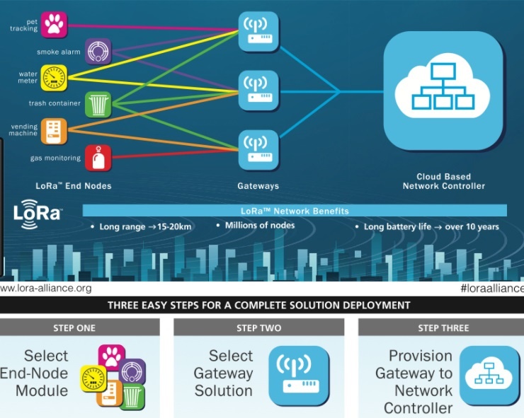
NOTE: A list of common terms and definitions have been included at the end of this post as a Glossary.
Using the infographic above, sensor connecting to the internet is referred to as end–devices. Whenever the sensor takes a reading the device conditionally sends a signal (data packet) that the gateways to capture the data. Now that data at the gateway uses FSK (Frequency Shift Keying) to transmit that data as efficiently as possible to the server using a process called the Chirp Spread Spectrum (CSS). As the data packet from the end device enters the circuitry of the gateway, it comes in “chirps,” or symbols that represent digital information (like below). The chirp is then parsed down to the frequency domain and then a modulated signal to efficient data transport.

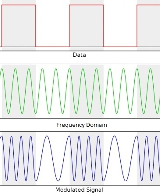
The LoRa hardware, after converting the input signal to the frequency domain, is searching within the frequency band for other,better frequency channels that can carry the signal. Once the gateway finds one, this whole process modulates the input signal’s frequency to make it more energy efficient, and then “shifts” (hence the “S” in FSK) the signal to that channel for quick data transmission.
The end-devices and gateways continuously interact with each other so that the data transmission can “hop” to other frequency channels that best suits the system’s power, speed, duty cycle, and range restraints.
During this frequency modulation, other integrated circuits within the LoRa gateway performs other “improvement” modulations, like filtering out noise, or the jaggedness that you see in a signal.

Another reason why LoRaWAN is a low-power, long-range network is thanks to a process called ADR (Adaptive Data Rate). Just like how the FSK process “shifts” the input signal frequency to boost efficiency, ADR “talks” to the LoRaWAN network server to boost the data rate. This is how the “talking” is done between device and server:
- The end-devices (nodes) constantly send uplink messages to the network server of LoRaWAN. These uplink messages are comprised of lots of information about the node’s past 20 signals
- The network server analyzes the recent history of the node and makes comparisons to see how much “margin” there is to make changes
- The network may observe that there is a “margin” for sacrificing range for something more useful, like a faster data rate. (Notice from the diagram that the trash can is sending its data to more gateways than any of the other devices)
- Instead of sending slower messages to far away gateways, the server would rather have the end device send a quick message to one gateway nearby.
- Hence, the ADR process takes advantage of opportunities that will boost the data rate. If the sacrifices being made helps the system operate more efficiently, then the sacrifice will be made using ADR.
After the gateways receive and interpret a data packet using LoRa technology, the gateway forwards the data to the network server via standard IP connections, like Ethernet or 3G. If the network server receives the same data packet from several gateways, it will only process one of them, and disregard the copies. Hence, if the server will receive three of the same data packet because the trash can is connected to three gateways in our illustration, then only one of these data packets will be processed, making for a highly accurate and very efficient data transfer.
Tradeoffs
As in every engineering application, there are trade-offs in the world of LoRaWAN when it comes to power, speed, and range. This simple diagram below displays the points of consideration.
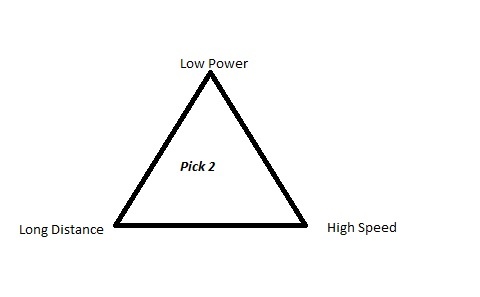
Increasing time of data bit ——-> reduces data rate ——-> lower speed
Decreasing time of data bit ——-> increases data rate ——-> higher speed
Increasing the range and reducing power ——-> lower speed
Increasing the range and quickening the speed ——–> requires higher power
Increasing the speed and reducing power——-> shorter range
Frequency Bands
LoRaWAN uses lower radio frequencies at a longer range, and the frequency bands differ between countries.
- Europe: 863-870 MHz and 433 MHz bands (868 MHz used by The Things Network). Three common 125 kHz channels for the 868 MHz band (868.10, 868.30 and 868.50 MHz) must be supported by all devices and networks.
- USA: 902-928 MHz band, divided into 8 subbands. Each of these subbands has eight 125 kHz uplink channels, one 500 kHz uplink channel and one 500 kHz downlink channel. As opposed to Europe’s frequency channels, those of USA are classified as uplink and downlink channels
- Australia: 915-928 MHz band. Uplink frequencies in Australia are on higher frequencies than in the US band. However, the downlink frequencies are the same as in the US band.
- China: 779-787 MHz band, with three common 125 kHz channels (779.5, 779.7 and 779.9 MHz), and also there exists a 470-510 MHz band, with 96 uplink channels and 48 downlink channels
Classes
LoRaWAN categorizes its end-devices in three different classes to address the different needs reflected in the wide range of applications.
Class A:
- these devices support bi-directional communication between a device and a gateway
- lowest power category
- Class A devices function only in applications where they send an uplink transmission and wait for downlink communication from the server shortly after
- uplink messages can be sent at any time
- after sending an uplink message, Class A devices open two receive windows at specified times
- the server can respond in either window
- the transmission slot (time slot) scheduled for each window by the end-device is based on its own communication needs
- if the server does not respond in either of these two receive windows, the next opportunity will be after the next uplink transmission
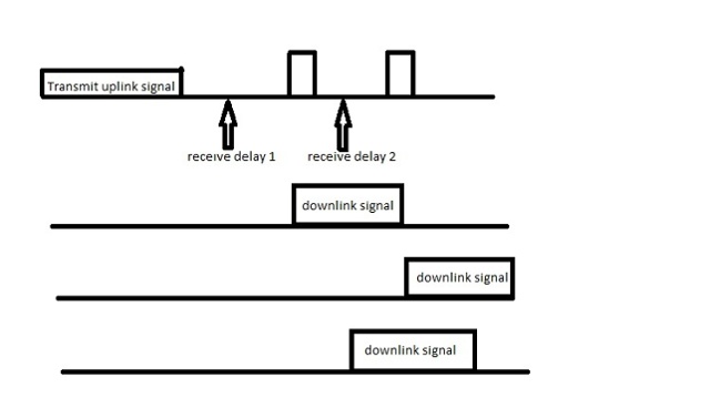
The first line in the diagram is the chronological process of the class A end-device uplink/downlink process. First, it is sends an uplink signal, waits, then opens up the first receive window; waits again, then opens up a second receive window. The next two lines demonstrate successful reception of a downlink signal after the downlink signals are captured by the receive window. The last line demonstrates unsuccessful reception of a downlink signal because it is not captured by the end-device in either receive window.
Class B:
- Class B end-devices are bi-directional with scheduled receive slots, like Class A
- The difference: Class B devices open extra receive windows at scheduled times in addition to Class A’s receive windows
- Unlike Class A devices, which open their receive windows based on their own communication needs, Class B devices receive a time synchronized beacon from the gateway, allowing the server to know when the end-device is “listening”
Class C:
- Class C devices are bi-directional with maximal receive slots
- These devices almost have continuously open receive windows, which are only closed when transmitting
- This allows for low-latency communication but is many times more energy consuming than devices in Class
Over-The-Air-Activation (OTAA)
To participate in a LoRaWAN network, each end-device has to be personalized and activated. The functionality of this process is summarized in these steps:
- For over-the-air activation, end-devices must follow a join procedure prior to participating in data exchanges with the network server.
- The join procedure requires the end-device to be personalized with the following information before it starts the join procedure: a globally unique end-device identifier (DevEUI), the application identifier (AppEUI), and an AES-128 key (AppKey).
- The join procedure consists of two MAC (media access control) messages exchanged with the server, namely a join request and a join accept.
- The end-device sends the join-request message consisting of AppEUI and DevEUI of the end-device followed by the DevNonce.
- The join-request message can be transmitted using any data rate and following an efficient frequency hopping sequence across the specified join channels.
- The network server will respond to the join-request message with a join-accept message if the end-device is permitted to join a network.
- After activation, the following information is stored in the end-device: a device address (DevAddr), an application identifier (AppEUI), a network session key (NwkSKey), and an application session key (AppSKey).
If step 7 is successful, OTAA is accomplished.
Activation by Personalization (ABP)
Under certain circumstances, end-devices can be activated by personalization. Activation by personalization directly ties an end-device to a specific network, by-passing the join request – join accept procedure. So, opposite to that of OTAA, the DevAddr and the two session keys NwkSKey and AppSKey are directly stored into the end-device instead of the DevEUI, AppEUI and the AppKey. Simply, the end-device is already equipped with the required information for participating in a specific LoRa network when started.
The advantage of ABP is that it is easy to connect to the network because the device can be made operational in little time, which is very suitable for certain applications. The disadvantage is that the encryption keys enabling communication with the network are pre-configured in the device, which weakens security.
Conclusion
To summarize, the key points of LoRaWan:
- LoRaWAN covers long distances, making it ideal for both urban and rural solutions
- LoRaWAN consumes less power which makes the technology ideal for battery powered devices
- LoRaWAN provides low bandwidth communication which makes it the ideal solution for practical IoT deployments that require less data
- Relatively low deployment costs compared to mobile or WiFi due to the lower number of Gateway devices required
- LoRaWAN supports bi-directional communication
- A single LoRaWAN Gateway can accommodate 1,000s of devices or nodes, multiple Gateways provide resilience to smart solutions
Glossary of Terms
Refer to this section for definitions of technical terms to aid you in understanding LoRaWAN. For your convenience, these words will be bolded in the tutorial when used.
Adaptive data rate (ADR): mechanism for optimizing data rates, airtime and energy consumption in the network
AppEUI:is a global application ID that addresses space and uniquely identifies the application provider (owner) of the end-device.
AppKey: an AES-128 application key specific for the end-device that is assigned by the application owner. The AppKey is used to derive the session keys NwkSKey and AppSKey specific for that end-device to encrypt and verify network communication and application data.
AppSKey: is used by both the network server and the end-device to encrypt and decrypt the payload field of application-specific data messages
Band: a range of frequencies with a specific least frequency and greatest frequency
Bandwidth: measures how much data can be sent over a specific connection in a given amount of time (synonymous with data rate)
Chirp Spread Spectrum: a type of modulation technology that is responsible for the reliability of the transmission as well as low power consumption
Cloud: a platform designed to store and process IoT data. The platform is built to process massive volumes of data generated by devices, sensors, websites, applications, customers and partners and initiate actions for real-time responses.
Data rate: the amount of digital data that is moved from one place to another in a given time; can be viewed as the speed of travel of a given amount of data from one place to another, based on how wide the bandwidth is
DevAddr:contains a network identifier (NwkID) to separate addresses of territorially overlapping networks of different network operators and to remedy roaming issues. It also contains a network address (NwkAddr) of the end-device.
DevEUI: a global end-device ID address space that uniquely identifies the end-device
DevNonce: a random value associated with an end-device. If an end-device tries connecting to the server with a DevNonce value that it has already previously used before, the server will ignore the request, preventing a system catastrophe known as replay attacks
Downlink: the link (connection) from a satellite to a ground station. Frequency of downlink signals tend to be broader to cover a large area on earth and provide as many services as possible
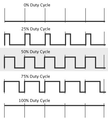
Duty Cycle: the percentage of the ratio of pulse duration, or pulse width (PW) to the total period (T) of the waveform. Duty Cycle = PW/T * 100%
Here’s a diagram to help you better visualize what a duty cycle is:
End-device/Node/End-point: an Internet-capable computer hardware device. The term can refer to desktop computers, laptops, smart phones, tablets, thin clients, printers, or literally any object that can connect to the internet
Frequency channel: when a band is channelized, that means there are specific discrete frequencies that a device (like a radio) will use and transmit data on. Instead of arbitrarily choosing random frequencies to use within the band, a device or network will stick to a certain step size to boost efficiency and avoid wasting gaps between different frequencies. For example, for a band 28-29 MHz, 3 different 100KHz channels could be 28.1 MHz, 28.2 MHz, 28.3 MHz, etc
Front-end: users (like a human being, or a program) interact with the application directly
LoRa: a proprietary, chirp spread spectrum (CSS) radio modulation technology for LPWAN used by LoRaWAN. LoRa is the physical layer, LoRaWAN is the network
LoRaWAN(Long Range Wide Area Network): a media access control (MAC) layer protocol for managing communication between LPWAN gateways and end-node devices, maintained by the LoRa Alliance
LPWAN(Low-Power Wide Area Network): a wireless wide area network technology that is specialized for interconnecting devices with low-bandwidth connectivity, focusing on range and power efficiency
NwkSKey:is used by both the network server and the end-device to calculate and verify the MIC (message integrity code) of all data messages to ensure data integrity.
Throughput: a measure of how many units of information a system can process in a given amount of time
Uplink: the link (connection) from a ground station up to a satellite. In IoT applications, signals must cross the atmosphere where attenuation is inevitable (from rain, for example). To avoid as much attenuation as possible, stations on earth boost their uplink signals with more power so that the frequency is narrower (so the signal could “fit” through obstructions in the environment). Hence, uplink signals generally have higher frequencies than downlink signals.

